By Tracy Mosley
Note: This article is one in a technical series by Trenchant of L3Harris Technologies.
Ghidra was originally developed by the National Security Agency as a reverse engineering framework, similar to IDA Pro. In 2019 it was released and is now FOSS. It has many processor specifications implemented already, but it is not an exhaustive list. Thus, a new processor module had to be implemented for my particular needs.
Having had the opportunity to guide an intern through the process of adding an ISA recently, as well as doing this myself, I plan on breaking down all of the steps of implementing an ISA in Ghidra. First of all, while other binary analysis tools are out there, Ghidra is free and some of us prefer to utilize more accessible tools. Ghidra is available https://github.com/NationalSecurityAgency/ghidra.
In addition to installing Ghidra, the architecture modifications will likely require a compiler program which is included in the base Ghidra on github. The package also includes documentation of the Ghidra DSL called SLEIGH, as well as trainings on how to utilize Ghidra. There are two plugins for the Eclipse IDE that exist with the base Ghidra package; one plugin called the GhidraSleighEditor is particularly helpful. It can be found in <GhidraInstallDirectory>/Extensions/Eclipse/GhidraDev/. Note that as mentioned in the Ghidra docs, the extensions only work with Eclipse IDE for Java and DSL Developers. The SLEIGH Editor allows for some error catching prior to compilation time or runtime, which significantly reduces troubleshooting time.
To extend an ISA in Ghidra one must become extremely familiar with the instruction set. For some architectures, the documentation can be left wanting. (ARM is still the exception with their fantastic, verifiable documentation.) Fully understanding the documentation for an architecture requires many read-throughs and often filling in the gaps, or correcting typos and misprints. It’s an unfortunate truth. Once the particulars of the specific architecture are understood, then one can move on to working with Ghidra. I often keep all ISA docs open throughout the Ghidra extending process.
SLEIGH and sinc files
Architecture documentation contains the particulars such as different instruction sizes, how the registers are organized, any coprocessors, virtual memory, register and address sizes, etc. Using this information, a .slaspec (and perhaps .sinc) file can be modified or created. The .slaspec file may include .sinc files using a preprocessor directive.
The files necessary for any architecture modifications are located in <GhidraInstallDirectory>/Ghidra/Processors/<ISA>/data/languages/* as indicated below, with the target architecture in the name of the file.
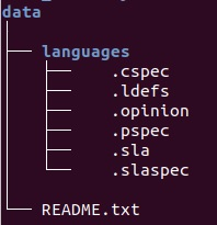
SLEIGH is a processor specification language specifically designed for Ghidra. The documentation for SLEIGH can be found at <GhidraInstallDirectory>/docs/languages/html/sleigh.html and it is recommended to keep this open for reference. According to the docs, “SLEIGH is a language for describing the instruction sets of general purpose microprocessors, in order to facilitate the reverse engineering of software written for them.”
The .slaspec is the file that utilizes the SLEIGH language to set up the specifics of the machine, which is why it is covered first in this blog. A familiarity with SLEIGH is required, but the basics will be covered here. This file is located at <GhidraInstallDirectory>/Ghidra/Processors/<ISA>/data/languages/*.slaspec. At the beginning of the .slaspec processor specifics such as the endianness, alignment, and sizes are defined. In fact, the first definition in the .slaspec must be for endianness. Since this is the case, I recommend having two separate .slaspecs: one for Big Endian, and one for Little Endian. For more on this approach, look at the base MIPS files provided in <GhidraInstallDirectory>/Ghidra/Processors/mips/data/languages/
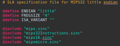
The above image is the entire mips32le.slaspec. (Spoiler alert: the only difference for the big endian file is the word “little” becomes “big”.) While the instruction processing portions can be included in .slaspec, most real processor implementations rely on .sinc files. The .sinc files allow extensions and variants for architectures to be broken out into individual files. In my approach, we utilized .sinc files for the tokenizing of a variant and a separate .sinc file for a DSP module which allowed for easier compilation and debugging.
Note how the above example indicates the separate file inclusion. SLEIGH supports several preprocessing functions including file inclusion (as seen above), preprocessor macros, and other basics such as conditional compilation. All of these directives begin with ‘@’ at the start of the line. Preprocessor directives allow for expansion utilizing $(VARIABLE) syntax.

Generally, the .sinc or .slaspec files will be the bulk of the required additions or modifications. In this paradigm, .sinc includes architectural definitions, pattern matching with display components (tokenizing and matching mnemonics to bit patterns), and semantics sections to ensure the instructions behave as the processor spec intends. The architectural directives are at the start of the file. Using 'define space' keywords and relying on the ISA spec for sizing, we declare the spaces. The type of space should be defined as ram_space, rom_space or register_space. Obviously, the more explicit information the better. (And here is that preprocessor expansion referenced above!)
Using 'define space' keywords and relying on the ISA spec for sizing, we declare the spaces. The type of space should be defined as ram_space, rom_space or register_space. Obviously, the more explicit information the better. (And here is that preprocessor expansion referenced above!)

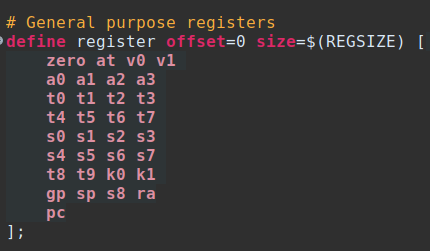
The next step is dependent upon what already exists in the base ISA. Defining registers requires knowledge of the architecture. It is very likely that Floating Point Registers (FPRs) will need a separate definition, as well as different sizes, etc.
First, to define registers explicitly, we use "define register" along with the offset and register list. If you’re extending a preexisting architecture, this will likely already exist and you may be able to skip this.
Next, I recommend creating context bits, tokens, and then attaching variables, in that order. Again, if extending an already existing ISA this may only require minor changes.
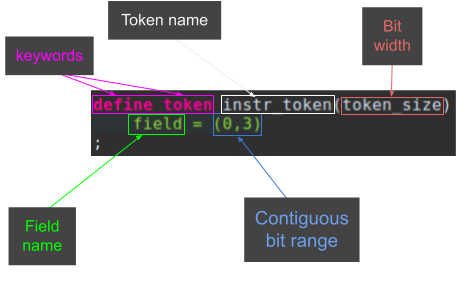
I recommend going through the ISA documentation and creating tokens and fields as needed for each instruction. Fields are inclusive, contiguous bit ranges. They are named, can repeat, may have overlapping bit ranges and are used in pattern matching. Fields are bound to bit ranges. Bit ranges are indicated by (startInt, endInt). The fields will apply to both tokens and contexts. Both the token fields and context fields must be unique.
field = (0,3)
Context registers may be, as in my experience, particularly useful and not straightforward. When expanding an existing base architecture, be sure not to clobber context bits in the register. Context registers come in handy when a processor utilizes a certain bit to indicate something about the state of the processor (e.g. 32 vs 64 bit mode, or endianness). These bits are highly necessary when the same instruction can exist in multiple modes, and Ghidra will need to determine which ‘mode’ to decode it. (When compiled, Ghidra will display context bits to the left of a ':' in the display.) Contexts are also useful for when bits span two sets of tokens and must be concatenated in order to be able to be read (e.g. a register spanning byte boundaries). You may need to add these as you go along in implementation. The context syntax is as follows:
define context contextreg
fieldname=(integer, integer) attributelist

Tokens are named, sized in BITS, and contain specific fields. Tokens rely on the keywords ‘define token’ followed by a name and size. Many processors will have several tokens for different instruction sizes. (How to use fields from different tokens in bit pattern matching is explained below.) I tend to utilize field names to represent exactly how the specification defines instructions.

Notice how the SleighDev plugin for Eclipse alerts the user that token_size should be an integer and not a string.
To review:
I look at an instruction, take note of the pieces that comprise it, define the necessary registers (and attach them, which we will cover subsequently), and create a field based on the syntax used in the instruction itself in the manual, filling in the appropriate tokens. I recommend doing this step for all instructions, having the SLEIGH token fields match the instruction fields in the processor spec as closely as possible, prior to moving on past tokenizing.

Example Instruction: ADD rt, rs, rd
In the above example, I would utilize descriptive names for fields. If there is no reasonable field name for me to remember, I suggest relying on bit positions. For example:
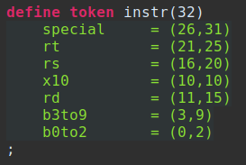
For my architecture, the bits were processed in chunks of 16, not 32 bits. Thus, I had to create two separate tokens accordingly. Using the same instruction example to illustrate, this would equate to splitting the fields into two separate tokens.
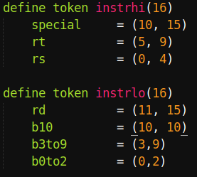
I prefer to think in this endianness, especially since it matches the field syntax, but you may prefer the opposite naming (b9to3) as the field name. When dealing with multiple instruction sizes, I highly recommend having the fields and tokens contain the size, especially when dealing with instructions of different sizes, or using multiple tokens per instruction. In other words, the above would be rd_32 for the field and instrhi_32 for the token. It also helps keep things straight when the instructions are 32-bit, but the processing is in 16-bit chunks. For the sake of simplicity, the size details will be omitted for future examples. Continue writing all of the tokens for each instruction prior to moving on to the next step.
Now is the point in the file where registers have been defined and should be attached. This is done by using the keyword ‘attach’. Once complete, the field can be bound to a space separated list of register identifiers. Context variables may also be attached. In my implementation, I needed to utilize context registers since my registers spanned token sets, or were not contiguous bits.

Once the basics of the processor are set up, the next step is creating each instruction out of specific components. Actually creating the instructions will require subconstructors, constructors, macros, and the final coding semantics piece. The bulk of the work will be in this portion, especially for extending architectures that already have registers bound, and don’t differ in register bit positions.
Subconstructors are supremely helpful, named constructors. They can be used to combine tokens to create a new variable to reference. Using subconstructors is a great way to combine context registers, or combine fields from different tokens. For my implementation subconstructors were particularly useful to combine fields from different tokens into a subconstructor. The subconstructor syntax pattern is below followed by an example.
The name of the subconstructor is used for future references in the file. The display piece is what is displayed in the Ghidra disassembler. Between the ‘:’ and the keyword ‘is’ is all considered the display piece. The bit pattern matching piece is comprised of fields and other subconstructors. It is what the incoming bit pattern must match in order to apply to this subconstructor. In the above example, rd will be displayed when the bit pattern matches the field of rd. This syntax will be used in future examples, so these pieces may be more clear.
The bit pattern matching piece of the subconstructor gets more complex when the bit pattern for the instruction is more complicated. When using fields from the same token, the ‘&’ is utilized to indicate logical AND, and ‘|’ indicates logical OR. Using fields from different tokens uses a ‘;’ to separate.
The example below will show how a subconstructor is created to concatenate rt and rd from the two different tokens documented above as instrhi and instrlo:

This example also demonstrates the use of the optional disassembly action piece. The optional disassembly action piece is what will be displayed to the Ghidra user in disassembly. The SLEIGH docs indicate the most obvious use of this as relative jumps, because the relative address should be what is displayed to the user. The example above is another instance of when the user would want to see a value calculated at disassembly time.
The disassembly action piece behaves slightly differently than the semantics section. The chart for Pattern Expression Operators is found in section 7.5.2 in the SLEIGH documentation. Most notably, ‘|’ and ‘&’ are bitwise operators, not logical operators.
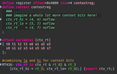
If, for some reason, the register rt exists in separate bit fields, and not in a contiguous range, the context bits are required. In the below example, the token field creation for rt_02 and rt_3 is omitted. This example would apply if rt’s low bits (bit 0 – bit 2, inclusive) were separate from rt’s highest bit (bit 3). Notice how the context bits are split into high and low and then have a combined field. For the sake of completeness, the ‘attach variable’ example is included:
Constructors are unnamed, but otherwise very similar to subconstructors. Technically, each constructor is part of a table. Thus, the first portion of a constructor is the table header. This table header starts the constructor and contains everything until a ‘:’ is encountered. However, if the constructor is part of the root instruction table, it will instead have the mnemonic first.
Just like for subconstructors above, between the colon and the keyword ‘is’ is the display piece. The bit pattern matching piece is after the 'is' keyword. The semantics section will be covered in more detail after a few more examples.
:<mnemonic> <display piece> is <bit pattern> { semantics }
Using the same example as above for ADD rd, rs, rt

Here is an example constructor with traditional 32-bit processing. Note the use of only the ‘&’ showing that all the bit pattern matching elements are fields from the same token (special, b10 etc) or are subconstructors (RT, RS, RD). The display piece shown is what the architecture specification shows as the ‘assembly’ piece and thus what the Ghidra user will be shown in the listing.

Here is the same instruction with the separate token fields separated by a ‘;’ if it were done in 16-bit processing format.

Here there is something of note in the bit pattern matching section. The ‘special=0x08’ is the way to implement constraints such that SLEIGH knows what conditions will match this particular constructor. The most obvious use of this is for an opcode. Below is an entirely made up example utilizing some of the pieces in bit pattern matching.
lso of note is that this example shows both integer and hex values being used for constraints. Binary is also a valid format. Also of note is that this example shows both integer and hex values being used for constraints. Binary is also a valid format.
The interior of the ‘{}’ is the semantics section, which will be addressed later.
One instance that was not mentioned above is that occasionally a bit pattern matching section will require using a subconstructor containing fields from multiple tokens. In order to include this subconstructor, the special case of ‘...’ is used. A good example of this is a LOAD instruction.
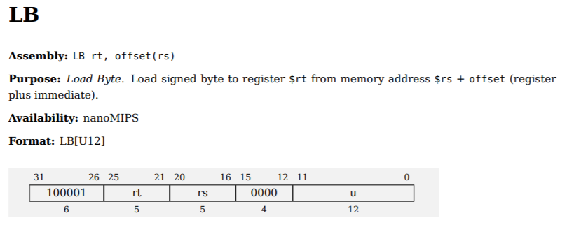
First is an example with 32-bit processing for the mnemonic of LB is shown below for contrast. This would obviously be the simplest option if possible. Below that is the 16-bit processing with the subconstructor required.

32-bit processing LB construction example
You may have noticed that the LOAD instruction must access memory. In order to do this Ghidra has some specific operators for the semantics section. The semantics section describes how the processor would behave with respect to data after matching the constructor. The variables inside the semantics section must be included in the bit pattern or globally accessible.
According to the SLEIGH documentation, “[f]or decompilation, SLEIGH describes the translation from machine instructions into p-code. P-code is a Register Transfer Language (RTL), distinct from SLEIGH, designed to specify the semantics of machine instructions. This provides the foundation for the data-flow analysis performed by the decompiler.” In other words, p-code is the intermediate language used for decompilation. The SLEIGH documents specifically mention semantics in section 7.7, stating “There is a direct correspondence between each type of operator used in the statements and a p-code operation. The SLEIGH compiler generates p-code operations and varnodes corresponding to the SLEIGH operators and symbols by collapsing the syntax trees represented by the statements and creating temporary storage within the unique space when it needs to.” Thus, there are two large tables in section 9 for operations and statements as well as expressions, which are labeled as p-code but apply to semantics. Those tables can be found in <GhidraInstallDirectory>/docs/languages/html/sleigh_ref.html. The two tables contain necessary information for mimicking the processor’s behavior. The existing operations are everything from extracting bit ranges, logical and bitwise operations, to absolute value and mathematical operations.
In the p-code documentation mentioned above, the LOAD syntax looks similar to the semantics in the last example. In the semantics piece of the example, it is dereferencing OFF_RS_U12 as a pointer into ram space, for 1 Byte. (It is also sign extended.) A bit more of an explanation:
| *v1 | Deref v1 as pointer into default space |
|---|---|
| *[space]v1 | Deref v1 as pointer into specified space |
| *:2 v1 | Deref v1 as pointer into default space with size of 2 bytes |
| *[space]:2 v1 | Deref v1 as pointer into specified space for size of 2 bytes |
User-defined operations are allowed as well. This allows for the Ghidra user to see the appropriate p-code and not require the semantics section to go through the actual procedure of performing actions as the processor. The SLEIGH documentation uses the example of arctangent, but below is an example of a syscall. Naturally Ghidra doesn’t need to actually make a syscall, but using this pcodeop will allow a user to see that one is in the file being analyzed.

User defined p-code can be useful to display to users a variety of things and can even display functions with parameters, as below.

The semantics sections can become quite complex. There are a lot more keywords and operators; see the SLEIGH documentation for more specifics (especially things like build directives, conditional codes, goto, call, etc).
In general in programming it is often helpful to break out portions of a larger section into smaller elements. That’s where Macros come into play. Macros are useful for encapsulation. In the semantics section, a macro can be called directly. As the documentation notes “[a]lmost any statement that can be used in a constructor can also be used in a macro.” There is no return from macros, but since parameters are passed by reference, the values of the parameter can be modified. The pieces of a macro are the keyword ‘macro’, followed by the global identifier the user is creating, followed by a comma separated parameter list. All in all, this looks quite C-like. The example below shows concatenating two pieces of an 8-bit value together:

Note that ‘final’ is passed in such that the value changes and can be used in the semantics section of the calling constructor.
Hooray! That should be all the building blocks you need for SLEIGH itself. As with any coding project, compile often to verify correctness. Again, the Eclipse plugin is also helpful for error and warning detection.
A follow-up blog post will cover how to compile using SLEIGH, but before that, there are a few more files. Other files that are necessary include .pspec for processor specifications, .cspec for compiler specifications, and .ldefs to tie the language together as a unit.
.pspec files
One necessary file is the .pspec file for processor specifications. You can use one or many of these files. The XML file that this must fit can be found in <GhidraIinstallDirectory>/Framework/SoftwareModeling/data/languages/processor_spec.rxg
The .pspec may be empty, but can also enable several processor specifics. .pspec files can be customized such that changing the SLEIGH isn’t required. While not necessary, it is possible to hide registers, set the program counter, specify segmented memory, or set custom context and properties.
In the example below, PC is defined, context registers are set, registers are hidden, and program property details are entered. Again, these are not necessary for the implementation to work.

.cspec files
The .cspec file is used for compiler specifications. There should be one per compiler version. The compiler spec is useful for disassembly and analysis per processor. The XML file that this must fit can be found in <GhidraInstallDirectory>/Framework/SoftwareModeling/data/languages/compiler_spec.rxg. Additional information exists in Ghidra/Features/Decompiler/src/main/doc/cspec.xml
According to the documentation, “For a particular target binary, understanding details about the specific compiler used to build it is important to the reverse engineering process. The compiler specification fills this need, allowing concepts like parameter passing conventions and stack mechanisms to be formally described.” In the documentation there is also an example of how the .cspec associates the file and processor ID. To create a good .cspec file from scratch, it is recommended to read the entire document. .cspec files cover calling conventions, parameters (pentry), data organization, packing and alignment, and other complex compiler options. The examples below will highlight different portions of the mips32.cspec.
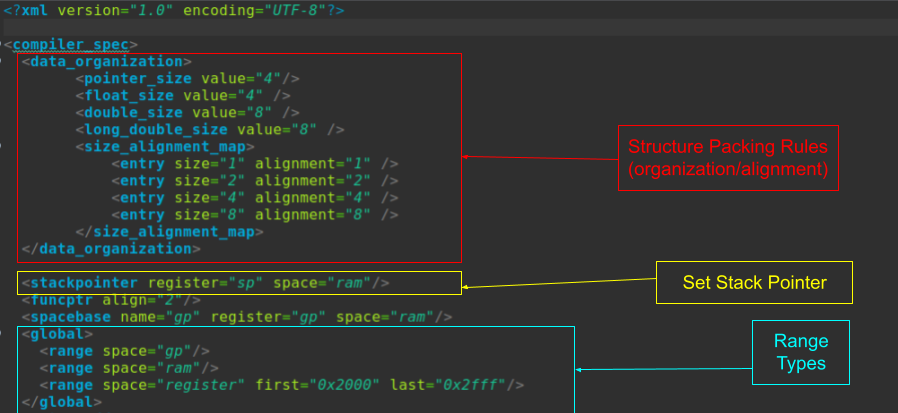
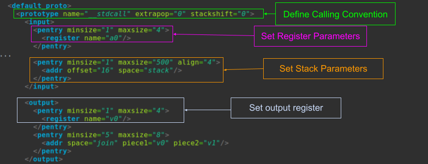
.ldefs file
The Language Definition file is what ties all of the pieces above together. The .slaspec (and .sinc), .pspec, and .cspec files are all linked together using this file. It is an XML file that describes the processor and what tools, compilers, descriptions and more are associated with it. This file is, I believe, what allows the user to select this architecture in Ghidra when importing a binary.
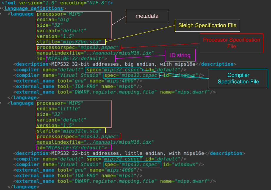
Other Optional Files:
There are a lot of other helpful files that are optional. For example, Opinion Files are helpful to guide the loaders for the architecture associated with each binary. <GhidraInstallDirectory>/Ghidra/Framework/SoftwareModeling/data/language/format_opinions.rxg shows the optional attributes for the constraints. A README.txt file is always helpful as well. ELF relocation handlers and function start/end patterns can also really help the autoanalysis built into Ghidra. However, the files mentioned above are the only necessary files to go forward with compiling and testing an ISA!