Integrated Platform Management Systems

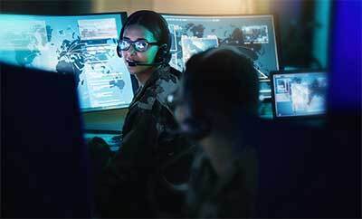
Today's warships have comprehensive platform automation capabilities that allow them to achieve unprecedented levels of ship survivability and operational effectiveness. Integrating these capabilities at the platform level can optimize operational effectiveness and contribute to crewing reductions. The L3Harris Integrated Platform Management Systems (IPMS) provides integrated monitoring and control of ship propulsion, electrical functions, auxiliaries and damage control machinery and systems.
In addition to the automation of these platform systems, additional features can be integrated into the IPMS such as:
- On-Board Training System (OBTS)
- Battle Damage Control System (BDCS)
- Digital Closed Circuit Television (CCTV) System
- Condition-Based Maintenance (CBM) System
System Architecture
The IPMS is a distributed architecture real-time digital control system. This open architecture system is comprised of multifunction control consoles and Remote Terminal Units (RTU). RTUs are used for process level data acquisition and control. The consoles provide the Human Machine Interfaces (HMI) for the operators at various shipboard locations. System-wide connectivity is provided by a redundant databus. A reliable multicast approach ensures integrity of data communication on the bus, while minimizing the bus traffic and providing very low data latency. Databus cables are strategically routed throughout the ship with adequate geographic separation to provide maximum system survivability. Open system architecture allows for the use of a variety of data networks in accordance with customer requirements. It also permits the interface of the IPMS to other systems through fieldbus, serial links, and other interfaces.
Data Acquisition and Control
We provide systems that can interface to as few as 100 signals and to a virtually infinite number of sensors and actuators. To manage this vast differential of signals, our IPMS provides a flexible and effective approach to data acquisition and control using variable density RTUs that are able to interface to a wide variety of sensors and actuators.
Such interfaces can be wired directly to the plant devices or can be provided through serial links and fieldbuses.
The RTUs are based on COTS open architecture electronic modules that integrate both signal conditioning and processing functions and provide optical isolation for field signals. The RTUs acquire plant sensor data, perform plausibility tests, check for limit violation, transmit the data to other IPMS subsystems as required, process automatic control sequences, output control signals to actuators, and perform online and offline built-in tests.
The automatic propulsion control and power management software resides in the RTUs together with control software for other platform machinery and systems. These units are ruggedized for installation in warship machinery spaces and can withstand the most stringent environmental conditions.
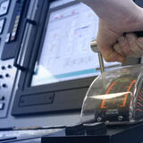
Gas Turbine Engine Controller
Using the same RTU hardware and software, we can also provide gas turbine engine controllers for a variety of gas turbines used on modern warships. Maintaining commonality with the rest of the IPMS architecture has significantly reduced life cycle costs for many navies by supporting the Engine Control Module (ECM) with the same training, spare parts, and upgrades available for the entire control system. The HMI associated with the gas turbine local controller can also be used for ship-wide control with all the capabilities of a console.
Data Logging, Trending, and Reporting
The IPMS continuously records the changes in sensor data and the control commands together with the date and time stamps for each value. Short-term data storage, comprising the last 24 hours, is available at each console, whereas long-term data storage can be provided by removable hard drives located inside specific consoles.
The data from these hard drives can be viewed on board and can also be analyzed in shore-based facilities.
Sensor information and other system data can be selected by the operator to be stored and displayed graphically together with the relevant alarm and warning limit thresholds. Either black-and-white laser printers and/or color printers can be provided to obtain hardcopy logs of events, alarms and the color graphic screens for archival purposes.
Battle Damage Control System (BDCS)
Management of vessel safety systems is achieved by the BDCS function which provides early damage recognition and effective coordination of damage control actions. BDCS functionality can include any or all of the following features:
Damage plotting
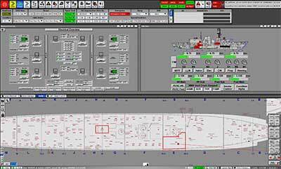
A replacement of the traditional damage control reporting system that uses sound powered phones and laminated damage control diagram plates. These plates are replaced by full ship, color diagrams with the ability to annotate standard damage control symbology. As damage information is acquired by the IPMS or entered at any console, all consoles are automatically updated. This provides the Commanding Officer, Engineering Officer, and the Damage Control Assistant with a real-time, complete, up-to-date picture of the damage situation giving them the information edge they need to effectively command the ship.
Kill cards
Kill cards are used to help the operator react quickly and correctly in the event of emergencies. Predefined automatic control sequences to respond to specific casualty conditions can be activated by the kill cards in addition to providing checklists for crew assignment and other damage management tasks.
Ship stability calculator
The ship stability calculator provides online expert system advice to ship personnel. This system can either accept sensor values or manual input to determine stability in both intact and damaged vessel conditions. This function calculates weight and momentum, lifting arms, hydrostatic values, and vessel motion during swells. Recommendations for improving ship stability are also provided by the system.

Digital CCTV System
To enhance the manpower reduction features of the IPMS, we have integrated a digital closed-circuit television system to provide video monitoring of the ship's machinery spaces and other locations. Full controllable PTZ and static cameras can be connected to the IPMS consoles using the existing network to allow the console screens to display the video image in a screen window, which can be maximized to use the full screen area. To provide the most flexibility, any camera can be selected for display on any console; however, fire alarms and flooding alarms will trigger the automatic display of the relevant camera images as specific consoles.
Condition-Based Maintenance System
Vibration monitoring systems and other specialized equipment and sensors can be integrated with the IPMS to provide periodic monitoring of equipment health. To facilitate the predictive monitoring of the machinery plant, expert system software is provided to advise maintenance personnel concerning the need for machine maintenance. Maintenance based on equipment health as opposed to periodic scheduling of maintenance has provided significant reductions in life cycle costs for ship owners.
The CBM system automatically monitors online accelerometers, tachometers, and displacement probes, and other sensors for critical machinery such as propulsion engines, shaft bearings, and generators. For less critical machinery, an offline portable vibration recorder with accelerometer can be used to transfer vibration data to the system.
On-Board Training Systems (OBTS)
Starting in the early 1980s, we used our extensive expertise in both simulation and controls technologies to pioneer IPMS on-board training functionality on warships. The IPMS can include an advanced OBTS capability whereby the operator consoles can also operate in training mode. All of the operator consoles (except one console to remain as station-in-control) can be placed in training mode to facilitate full-mission team training on board the ship. One of the consoles would be designated as the instruction facility while the other consoles are operated in training mode. If a console or group of consoles in control mode fails, the other consoles operating in training mode automatically revert to control mode.
The OBTS uses real-time high-fidelity simulation models of the ship's hull, platform machinery and systems and includes an emulation of RTU automation functionality. Previously defined training scenarios can be performed or new scenarios created by the instructor on board the ship. Except for the use of training data generated by real-time high-fidelity simulation techniques, the operator consoles behave exactly as they do during normal control mode operation using the same software. This ensures a very high level of training realism.

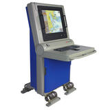
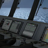
Human Machine Interfaces (HMI)
The IPMS includes advanced HMI design that is consistent with its application in a sophisticated warship. The primary HMI is in the form of multifunction control consoles, typically located in the machinery control room and on the bridge. Wall-mountable consoles are typically provided in damage-control section bases and for local control in the engine rooms and other machinery spaces. Portable operating units support emergency control operations and troubleshooting using built-in test equipment and software.
Control and monitoring from consoles is performed through the use of integrated control panels and high-resolution color monitors that display ergonomically designed graphical pages of the platform machinery and systems. Each console is multifunctional and can perform all functions of the IPMS, provided the appropriate password authorization is used and the control transfer protocols are respected.
This provides a very high level of survivability, as total platform control can be exercised from several widely separated locations on the ship.
L3Harris pioneered the use of color graphics-based machinery control for warships and has accumulated a significant amount of experience and expertise in the implementation of ergonomically designed color graphics pages. Well-reached symbology is preferred over the distracting effects of an extravagant use of color and artistically rendered symbols. The screens are designed to provide the necessary information to the operator with special emphasis on emergency conditions.
Our Tiled, Layered Graphics (TLG) approach facilitates the automatic decluttering of information at various zoom levels, ensuring easily readable displays at all times. TLG also provides a novel form of navigation through the ability to pan and zoom in a "world view" of the ship. Alternatively, a structured windows approach is used with four windows that can be displayed simultaneously on the screen, allowing the operator to manage several different systems at once.
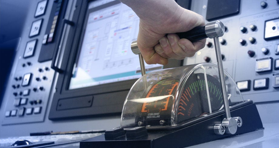
While the color screens make it possible to monitor and control every aspect of the platform, the IPMS can also include a limited amount of dedicated instrumentation for emergency control and monitoring from the control rooms. An engine order telegraph (EOT) system can also be included to communicate propulsion orders to the control rooms from the bridge. This is backed up by an emergency telegraph system with repeaters located in the machinery spaces. Several types of pages are used to display plant overviews, machinery data, system schematics, trending displays, alarms, events, and fault messages. The IPMS features elaborate alarm processing techniques that reduce operator loading by filtering out nuisance alarms and providing context-sensitive displays based on the nature and severity of the alarm. This feature is vitally important in systems that have a large number of sensors as it helps to maintain operator effectiveness under both normal and emergency conditions.
Audible and visual annunciation is used to alert the operator to the occurrence of alarms, warnings and faults. Acknowledgement of such annunciation is typically based on the function allocated to each position; that is, the propulsion operator (irrespective of his physical location in the ship) acknowledges propulsion alarms, warnings and faults.